In this lab, 000 was used as the sequence that encrypted inputs, and 111 as the sequence in which the outputs are decrypted. A state graph using a Moore state machine was created to visualize the present state and next states, and a state table was then created using the D flip flop. K-maps were made according to the state table. Boolean expressions were then derived from the K-maps and implemented into the Quartus II software to design a schematic that could be connected to the DE0-CV Board and perform the bitstream output.
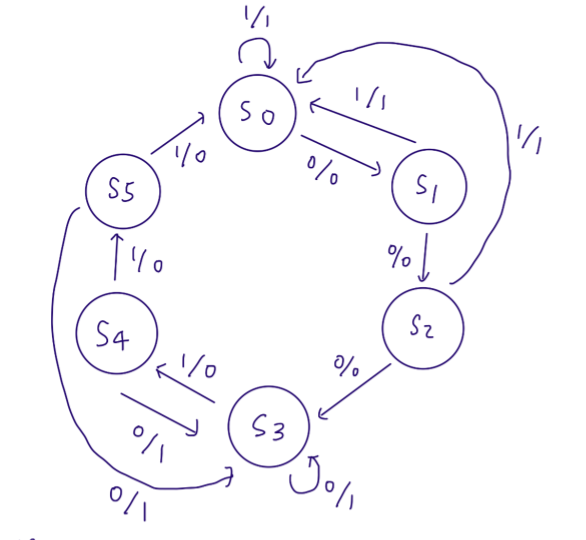
State Graph of the 000, 111 bitstream using Moore state machine
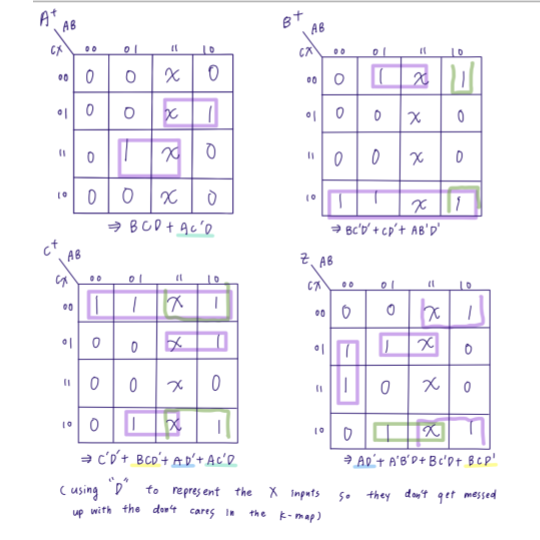
K-maps and Boolean expressions for each output
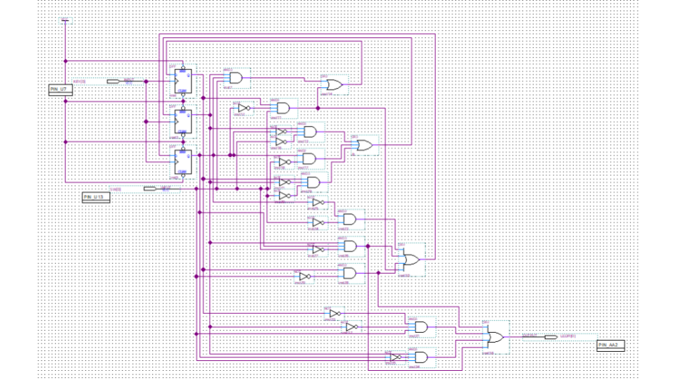
Schematic that performs the intended bitstream output